|
Standard engine bolt pattern vs. blind holes
|
| Joe Kriz |
Posted on 05/03/08 - 3:55 PM
|

Site Owner
Personal Page
Personal Album
Photo Albums
Project Albums
Posts: 11434
Comments:
452
Joined: 03/18/05
|
I posted this is another thread but wanted to get more exposure here.
I know many people have replaced their older engines that were mounted using the bottom "blind" mounting holes. In order to mount another engine without using the blind holes, we would need to raise the engine up and of course fill the lower holes in the transom from the original installation.
1. How far do we need to raise the engine (how many holes) so we can use the lower mounting slots for the lower mounting bolts?
2. What are the measurements for the blind holes as compared to the drawing below?
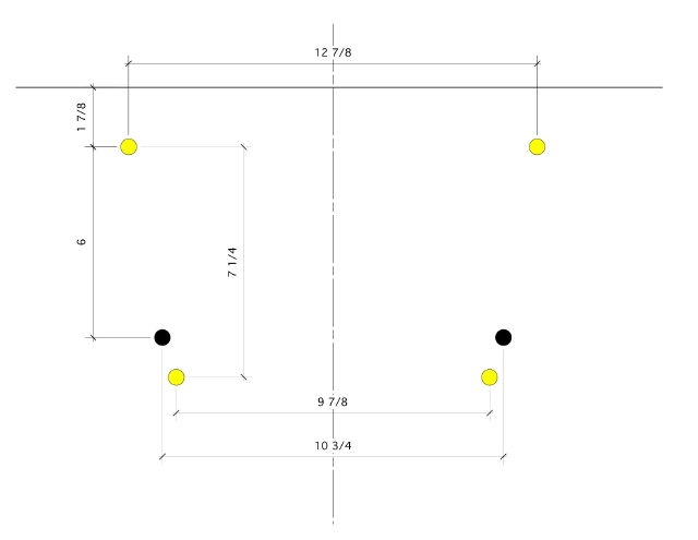
I made a simple drawing of the standard BIA mounting bolt pattern.
I also added other holes above the lower holes which are 3/4" apart.
Can anyone tell me where in relation to this drawing are the blind holes located?
[img]http://www.whalercentral.com/images/Mounting_Bolt_Pattern.jpg[/img]
How far down from the top of the transom are the blind holes located?
How wide are the blind holes as compared to the 9 7/8 inches of the standard bolt pattern?
|
| |
|
|
| Tom W Clark |
Posted on 05/03/08 - 3:59 PM
|

Member
Personal Page
Posts: 4280
Comments:
7
Joined: 09/30/05
|
Joe,
Good drawing.
The blind holes (really the holes for the bolts going in to the blind holes in the motor) are 6" o.c. below the upper mounting bolt holes. The spacing of the blind holes is 10-3/4"o.c.
Edited by Tom W Clark on 05/03/08 - 4:00 PM |
| |
|
|
| Joe Kriz |
Posted on 05/03/08 - 4:18 PM
|
Site Owner
Personal Page
Personal Album
Photo Albums
Project Albums
Posts: 11434
Comments:
452
Joined: 03/18/05
|
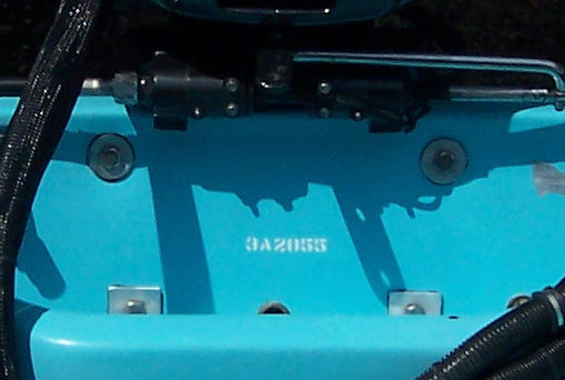
Here is a photo sent in by Russ using the blind holes thru the transom.
The splashwell is clear and the bolts can easily be accessed.
If you look very close at the bolt pattern and especially the lower bolts, you will see that the centerline of the lower bolts are just slightly above the splashwell drain.
These lower "blind" holes, according to Tom, are 6 inches o.c. below the upper mounting bolts.
If we did NOT want to use the blind holes, would raising the engine up 2 holes allow us to mount the engine and still have clearance in the splashwell? If we did raise the engine up 2 holes, then the distance to the lower mounting holes in the top of the slot would be 6 1/2 inches.
Is that enough? It looks like it would work from the attached photo. Maybe using a round washer instead of the square if that would make any difference.
Joe Kriz attached the following image:
[33.94Kb]
|
| |
|
|
| Tom W Clark |
Posted on 05/03/08 - 4:51 PM
|
Member
Personal Page
Posts: 4280
Comments:
7
Joined: 09/30/05
|
Joe Kriz wrote:
If we did NOT want to use the blind holes, would raising the engine up 2 holes allow us to mount the engine and still have clearance in the splashwell?
If we did raise the engine up 2 holes, then the distance to the lower mounting holes in the top of the slot would be 6 1/2 inches.
Is that enough?
Yes and yes.
|
| |
|
|
| Joe Kriz |
Posted on 05/03/08 - 5:02 PM
|
Site Owner
Personal Page
Personal Album
Photo Albums
Project Albums
Posts: 11434
Comments:
452
Joined: 03/18/05
|
Tom,
That's good news.
I redid the drawing to add the blind holes in black color.
I also colored the 2 holes green that would be 1/2 inch lower than the blind (black) holes.
I would like to hear from anyone with a 16/17' hull that has their engine raised up 2 holes.
How is the performance?
I know my 70 hp Evinrude was mounted all the way down and the engine was too low.
I always wanted to raise it but because it was mounted using the blind holes, I never did raise it up.
Apparently we cannot just raise the engine up 1 hole because the lower thru bolts will not clear the inside of the transom so we would have to raise the engine up 2 holes...
Anyone?
[img]http://www.whalercentral.com/images/Mounting_Bolt_Pattern.jpg[/img]
Edited by Joe Kriz on 05/03/08 - 5:04 PM |
| |
|
|
| Tom W Clark |
Posted on 05/03/08 - 5:08 PM
|
Member
Personal Page
Posts: 4280
Comments:
7
Joined: 09/30/05
|
Joe,
Your drawing is a little misleading. While different manufactures use different numbers of optional holes (some use four and some use five) and, in the case of OMC and some BRP motors, slots instead of holes for the lower mounting holes, let's just pretend there are four sets of holes.
Go ahead and modify your drawing to show all the holes and you will see that you have the lower holes in your drawing above where they actually are.
|
| |
|
|
| Joe Kriz |
Posted on 05/03/08 - 5:20 PM
|
Site Owner
Personal Page
Personal Album
Photo Albums
Project Albums
Posts: 11434
Comments:
452
Joined: 03/18/05
|
Yeah, the drawing is NOT to scale.
Just something I started playing with to get an idea.
The dimensions are correct now for all the holes.
I believe, but not positive, that all the mounting holes for engines are 3/4 inches apart?
Raising any engine up 2 holes will raise the engine 1 1/2 inches.
|
| |
|
|
| Tom W Clark |
Posted on 05/03/08 - 5:22 PM
|
Member
Personal Page
Posts: 4280
Comments:
7
Joined: 09/30/05
|
Yes, that is correct.
|
| |
|
|
| Joe Kriz |
Posted on 05/03/08 - 5:46 PM
|
Site Owner
Personal Page
Personal Album
Photo Albums
Project Albums
Posts: 11434
Comments:
452
Joined: 03/18/05
|
Here's another question.
Tom says we will have the clearance in the splashwell if we drill the lower holes 1/2 inch below the blind holes which would be 6 1/2 inches below the upper mounting holes. These are the holes shown in Green color.
Is is possible to drill the Yellow color holes which would put these holes down 7 1/4 inches below the upper holes? This would be 1 1/4 inches below the blind holes. Would there still be clearance in the splashwell for thru bolting these lower bolts?
|
| |
|
|
| Tom W Clark |
Posted on 05/03/08 - 5:53 PM
|
Member
Personal Page
Posts: 4280
Comments:
7
Joined: 09/30/05
|
Yes, you can do that too, but it gets real close to the bottom of the splashwell. The washers will need to have a "flat" cut on the bottom of them to nest into the bottom of the splashwell.
|
| |
|
|
| Joe Kriz |
Posted on 05/03/08 - 6:20 PM
|
Site Owner
Personal Page
Personal Album
Photo Albums
Project Albums
Posts: 11434
Comments:
452
Joined: 03/18/05
|
That's even better. This way your would only have to raise the engine 1 hole and then drill your lower hole (Yellow color) in the top of the slot or the upper lower hole for some engines.
I now my prior engine could have been raised 1 hole without any problems with cavitation. I was not sure it could go up 2 holes without having to start playing with the prop.
If a person does go up 2 holes and then drills the lower holes (Green color), the engine could not go down any lower with those existing holes.
My drawing is for the possibility of hole position in the transom only. It does not show the holes or slots for the engine bracket(s).
|
| |
|
|
| PaulTarwater |
Posted on 05/03/08 - 6:42 PM
|
Member
Personal Page
Posts: 140
Comments:
1
Joined: 08/25/07
|
All dialogue & measurements stated above should work but I found that I did not have enough room in the splashwell to use the slots on the engine bracket because I used the top bolt holes. Instead, I used the top holes of the motor bracket and the bottom two holes just a little above and to the outside of the slots...but below the 4 sets of holes on the very top of the bracket. Mine worked fine but there was no adjustment. There was room in the splashwell to through-bolt using the slots if the engine were raised to use the 3rd set of holes down from the top but I would have been cavitating. Paul
[IMG]http://i273.photobucket.com/albums/jj226/PaulTarwater/splashwell002.jpg[/IMG] [IMG]http://i273.photobucket.com/albums/jj226/PaulTarwater/splashwell001.jpg[/IMG]
Edited by Joe Kriz on 05/03/08 - 7:14 PM |
| |
|
|
| Tom W Clark |
Posted on 05/03/08 - 7:34 PM
|
Member
Personal Page
Posts: 4280
Comments:
7
Joined: 09/30/05
|
Paul,
Right, yours is the precisely the situation Joe is discussing a solution for. Your early 1970s lower bolts are in the position of the "blind" holes of later models, where the hole was a threaded blind hole into the casting of the motor mounting bracket.
You could raise your motor one or two bolt holes by using the strategies we are discussing here. You may well ventilate if your motor is raised two bolt holes *AND* you use the same prop you have now, but a good stainless prop will work fine two holes up.
The holes in the transom on a boat like your would look like these two drawings depending on if you went up one hole or two holes:
Tom W Clark attached the following image:
[18.08Kb]
Edited by Tom W Clark on 05/03/08 - 7:48 PM |
| |
|
|
| Joe Kriz |
Posted on 05/03/08 - 7:53 PM
|
Site Owner
Personal Page
Personal Album
Photo Albums
Project Albums
Posts: 11434
Comments:
452
Joined: 03/18/05
|
Well, I redid the drawing again so Tom and I can get our thought together. (maybe just me :-)
The black colored holes represent the 4 existing holes in the transom if your engine is mounted using the blind holes in the engine bracket.
The red holes are the standard BIA placement and cannot be drilled in 16/17' classic hulls due to the splashwell design. Do NOT drill the red holes.
If you raise the engine up 1 hole, and then drill the yellow colored hole, you might be able to do this and clear the inside of the splashwell according to Tom. (read above posts)
If you raise the engine 2 holes, and then drill the green colored hole, this will definitely clear the inside of the splashwell. At this point, the engine may or may not be mounted too high. Another prop with more gripping power may be needed. (again, read above posts)
[img]http://www.whalercentral.com/images/Mounting_Bolt_Pattern.jpg[/img]
-----
Paul, thanks for the photos and the input.
I don't think you can drill the newer engine brackets like you did with the older engine in your photos. I just don't think it is possible due to the design of the newer brackets.
------
We all know we could use a setback bracket and use the existing holes but that is NOT the discussion here. We could also use lag bolts but that is also another story.
If anyone has any other ideas or has raised their engine up 1 or 2 holes to do what we have been discussing here, please let us know.
|
| |
|